Replace the encoder with the Optical Mouse Sensor
Encoders are useful in measuring the speed and position of the wheel-robot. However, it also brings many headaches when designing the robot, especially on a small scale or with multiple wheels. You have to merge the value from all encoders, and in some cases, if there is drift, you will lose control.
In electronics, encoders require you to have a dedicated microcontroller (MC) or a bit complex control system (if you have to manage several motors with encoders in the same MC) for maintaining the position and speed of the motor output. This is easier said than done, and many students that I meet struggle to create a sustainable closed-loop control system.
Moreover, in some differential drive robots, it is always necessary to ensure that both wheel is the same diameter, but in reality, there is always a difference in size, which leads to angle drift after several runs. And it also took time for you to recalibrate all over again.
For drones, maintaining position using a camera system has been well developed, but for cars, I haven’t seen this trend yet. Perhaps there is some problem? There is some paper research about this, but not much. 1 2
Especially in a micro-mouse, where you will find that searching for a high-accuracy encoder and fitting it into a small footprint is crazy hard. That’s why I’m looking for a potential way to reduce the need for an encoder in a robot and perhaps remove the gyro too.
An Optical Mouse Sensor, or simply a Mouse, is what you use every day. It is a high-speed camera that captures a very small image of a small surface of your table and measures the position while you move it, and sends the signal to move the cursor on your ~`screen. For years, this technology has been significantly cheaper, only 2$ for a wireless mouse. And in some gaming mice, it can capture more than 10G of acceleration. This makes me feel that I need to put this sensor into a micromouse to see whether this is feasible.
After several usable mouse teardowns, I found that MX8650 is a usable sensor, so I quickly wired up this to test, but after several attempts, I didn’t get the output. I came to this page by ftukurou and got the workable code.
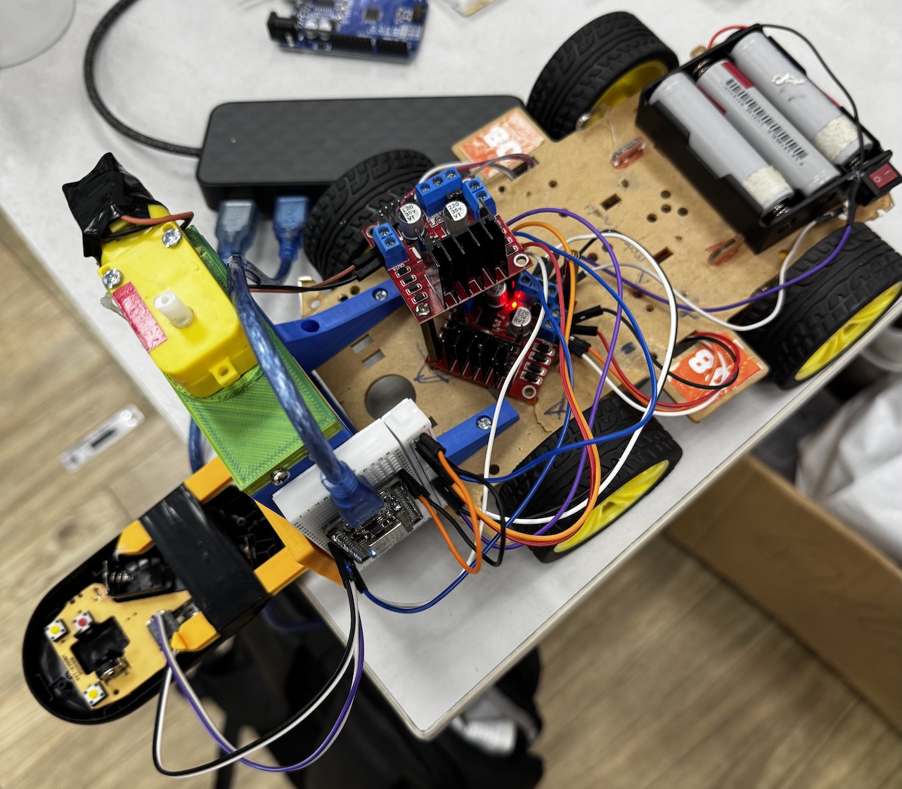
After that, I quickly modified the robot and saw if the sensor could keep this robot moving in a straight line. And the result is quite surprising, it works although the floor was not really flat. With 3-4 meters move, the robot drifts around 3-5 cm, which is pretty good for no calibration at all.
Below is my code, just in case. You need to follow the ftukurou instruction to modify the OptiMouse library first.
1
2
3
4
5
6
7
8
9
10
11
12
13
14
15
16
17
18
19
20
21
22
23
24
25
26
27
28
29
30
31
32
33
34
35
36
37
38
39
40
41
42
43
44
45
46
47
48
49
50
51
52
53
54
55
56
57
58
59
60
61
62
63
64
65
66
67
68
69
70
71
#include "ADNS2083.h"
#define SCLK 14 // Serial clock pin on the Arduino
#define SDIO 12 // Serial data (I/O) pin on the Arduino
#define _Config 0x06

ADNS2083 Optical1 = ADNS2083(SCLK, SDIO);

long long x = 0;
long long y = 0;

int left = 5;
int right = 4;

// PID parameters
float Kp = 0.3;
float Ki = 0.0;
float Kd = 0.02;

float prevError = 0;
float integral = 0;


// Base speed (PWM 0–255)
int baseSpeed = 80;

void setup()
{
Serial.begin(115200);
Serial.println("Initializing...");

Optical1.begin(); // Resync (not really necessary?)
// writeRegister(_Config,0x01); //CPI setting 800 0 / 1000 0x01 / 1200 0x02 /1600 0x03

delay(100); //Somehow. Maybe it's okay without it.

pinMode(left, OUTPUT);
pinMode(right, OUTPUT);

// analogWriteFreq(new_frequency);

}


void loop()
{

  x -= (signed char) Optical1.dx();
  //x =~ (Optical1.dx() - 1); // When the direction is reversed
  y += (signed char) Optical1.dy();
  Optical1.mo();				 //Motion_Status read

  // PID error calculation (want x = 0)
  float error = 0 - x;
  integral += error;
  float derivative = error - prevError;
  prevError = error;

  float output = (Kp * error) + (Ki * integral) + (Kd * derivative);

  // Motor speed adjustment
  int leftSpeed = constrain(baseSpeed - output, 0, 255);
  int rightSpeed = constrain(baseSpeed + output, 0, 255);

  analogWrite(left, leftSpeed);
  analogWrite(right, rightSpeed);

  Serial.println("Delta X: " + String(x));
  Serial.println("Delta Y: " + String(y));
  delay(10);

}